Spectrum Analysis
A noisy environment can cause the data in 802.11 transmissions to become corrupted -> the cyclic redundancy check (CRC) will fail -> the receiving 802.11 radio will not send an ACK frame to the transmitting 802.11 radio -> the unicast frame is not acknowledged
and will have to be re-transmitted. Wi-Fi data networks can handle a retransmission rate of up to 10 percent, but a Voice over Wi-Fi (VoWiFi) network needs to limit packet loss to a rate of 2 percent or less.
Sources of interference for 2.4GHz band
- Microwave ovens
- 2.4 GHz cordless phones, DSSS and FHSS
- Fluorescent bulbs
- 2.4 GHz video cameras
- Elevator motors
- Cauterizing devices
- Plasma cutters
- Bluetooth radios
- Nearby 802.11, 802.11b, or 802.11g WLANs
- Wireless Internet service providers (WISPs)
Sources of interference for 5GHz band
- 5 GHz cordless phones
- Radar
- Perimeter sensors
- Digital satellite
- Nearby 802.11a WLANs
- Outdoor wireless 5 GHz bridges
After locating the sources of interference, the best and simplest solution is to eliminate
them entirely.
Indoor use of 5.8 GHz phones will cause interference with 802.11a radios transmitting in the upper UNII band.
Currently, Wi-Fi VoIP phones operate using High-Rate DSSS (HR-DSSS) technology
and the radios therefore transmit in the very crowded 2.4 band.
Coverage Analysis
Proper coverage analysis must be performed using some type of received signal strength measurement tool.
The first mistake is leaving the access point radio at the default full power setting. Many legacy client cards have a maximum transmit power of 30 mW. The RF signal of a 30 mW client might not be heard at the outer edge of an access point’s 100 mW coverage cell. A good starting point for a 2.4 GHz access point is 30 mW transmit power.
Where to place the first AP:
- Place an access point in the corner of the building with a power setting of 30 mW.
- Walk diagonally away from the access point toward the center of the building until the
received signal drops to -65 dBm. Place the first AP here. - Temporarily mount the access point in the first location and begin walking throughout
the facility to find the –65 dBm end points (cell boundaries or cell edges) - Make any necessary power and AP position adjustments
Where to place the next AP:
- Start at the -65 boundary, Place an AP here
- walk away from this access point, parallel to the edge of the building, until the
received signal drops to –65 dBm. - Place an AP here (this is if you do not want cell overlap)
- Using the distance from the previous access point and this location, the placement of this next access point should be about 15 to 20 percent (depending upon cell overlap requirements) closer to the previous access.
- Move to that location and temporarily mount the access point and begin walking
throughout the facility to find the –65 dBm end points, or cell boundaries. - Again, depending upon the shape and size of the first coverage cell. Make any necessary power and AP position adjustments
The rest of the site survey is basically repeating this procedure over and over again, effectively daisy-chaining throughout the building until all coverage needs are determined.
Avoid excessive overlap as it causes frequent roaming and performance degradation.
measurements taken during the site Survey:
- Received signal strength (dBm), also known as received signal level (RSL)
- Noise level (dBm)
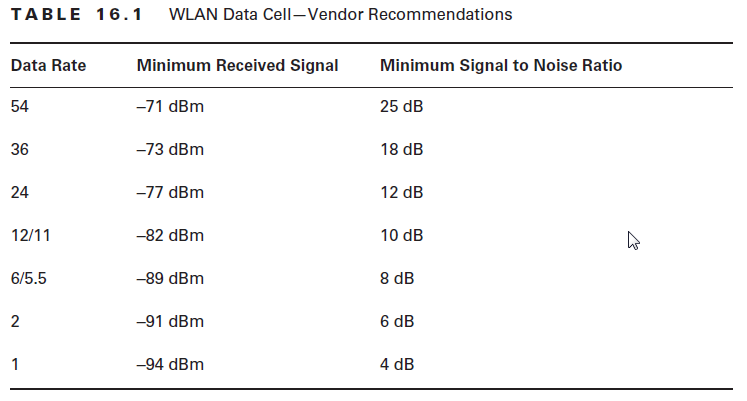
- Signal-to-noise ratio, or SNR (dB). if the background noise is too close to the received signal, data can get corrupted and retransmissions will increase. The SNR is simply the difference in decibels between the received signal and the background noise. Many vendors recommended a minimum SNR of 18 dB for data networks
and a minimum of 25 dB for voice networks. - Data rates. A site survey using just data rates or a proprietary signal strength measurement threshold does not allow for any flexibility between vendors.
VoWiFi recommended rates:
- RSSI > 70 dBm
- SNR > 25 dB
- 15 – 20 % cell overlap
- same channel cells should be > 20 dB
- Recommended coverage
AP Placement and Configuration
The use of semi directional antennas instead of the default low gain omindirectional antennas might come in handy in some places. When used in
areas where there are metal racks, file cabinets, and metal lockers it can cut down on reflections. Using indoor semi-directional antennas to reduce reflections will cut down on the negative effects of multipath, namely the data corruption caused by the delay spread and inter-symbol interference (ISI) leading to less data retransmissions and hence enhancing wlan performance. Combining different antenna types is the best way to provide proper coverage.
Application Analysis
This is usually optional.This can be used mostly when teating for wireless VoIP
References:
- CWNA Certified Wireless Network Administrator Study Guide by David D. Coleman and David A. Westcott.
