This week was a rather intense one. I offered to be a volunteer trainer for a Network Security Bootcamp whose aim was to provide practical experience to new graduates and prepare them for a job in the Network Security field. At the end of the course, the students are expected to pass several exams among which was the Comptia Network+ Exam. The topic of the week was Network Operations and we touched on VPN tunnelling. I spent a while wondering what labs I could prepare for them to give them the much desired practical skills. In the end, I remembered Cisco’s Packet Tracer. It has been more than 6 years since I used it so I was a little rusty, but I always say that once you properly understand networking, it’s really difficult to unlearn it. This blog is a summary of the hand-on lab that I prepared for the students. Hope someone will find it helpful.
Below is the topology that was used for this lab and steps taken by the students.
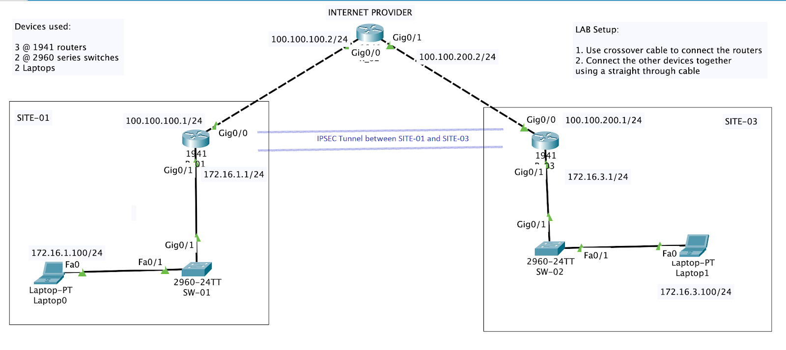
Initial Setup
1/ Use a crossover cable to connect the routers together. We are using the 1941 Routers for this topology.
2/ Connect the other devices together using a straight through cable connection.
3/ Perform initial router configuration.
Configure the interface IP addresses on the routers and a default route on R_01 and R_03 pointing to the R_02 router. The R_02 router acts as an internet provider and has no knowledge of other networks except its directly connected network.
    hostname R_01
    interface g0/1
    ip address 172.16.1.1 255.255.255.0
    no shut
    interface g0/0
    ip address 100.100.100.1 255.255.255.0
    no shut
    exit
    ip route 0.0.0.0 0.0.0.0 100.100.100.2

    hostname R_02
    interface g0/1
    ip address 100.100.200.2 255.255.255.0
    no shut
    interface g0/0
    ip address 100.100.100.2 255.255.255.0
    no shut
    exit

    hostname R_03
    interface g0/1
    ip address 172.16.3.1 255.255.255.0
    no shut
    interface g0/0
    ip address 100.100.200.1 255.255.255.0
    no shut
    exit
    ip route 0.0.0.0 0.0.0.0 100.100.200.2
4/ Ensure that the laptops have static IP addresses configured. Laptop0 should have IP 172.16.1.100/24. Laptop1 should have 172.16.3.100/24. Attempt pinging across from Laptop0 to Laptop1. This should fail as R_02 does not know how to route this traffic.


    !Laptop0
    ping 172.16.3.100

    !Laptop1
    ping 172.16.1.100
5/ Activate licensing on the edge routers. Ensure that you have the security license enabled on R_01 and R_03.
    show version
    license boot module c1900 technology-package securityk9
    copy run start
    reload
    show version
IPSec VPN Configuration
For the IPSec Tunnel to come up. The configuration on both ends need to be match for both Phase 1 and Phase 2 to be successful. The tunnel will be formed between R_01 and R_03.
1/ Setup an ACL that will specify which interesting traffic will be allowed to pass through the tunnel.
    !R_01
    access-list 100 permit ip 172.16.1.0 0.0.0.255 172.16.3.0 0.0.0.255

    !R_03
    access-list 100 permit ip 172.16.3.0 0.0.0.255 172.16.1.0 0.0.0.255
2/ Setup Phase 1 of the IPSec Tunnel. In this part, we define the ISAKMP policy and specify that we will use a preshared key. This is also defined in this case.
    !R_01
    crypto isakmp policy 10
        encryption aes 256
        authentication pre-share
        group 5
    !
    crypto isakmp key Secret-2020 address 100.100.200.1

    !R_03
    crypto isakmp policy 10
        encryption aes 256
        authentication pre-share
        group 5
    !
    crypto isakmp key Secret-2020 address 100.100.100.1
3/ Next, we setup phase 2 of the IPSec Tunnel (IPsec Transform-set). This is where the IKE negotiation takes place. We will be using 256 bit AES encryption with hash message authentication code providing confidentiality, integrity and authentication.
    ! R_01
    crypto ipsec transform-set R_01-R_03 esp-aes 256 esp-sha-hmac

    ! R_03
    crypto ipsec transform-set R_03-R_01 esp-aes 256 esp-sha-hmac
4/ All we need to do next is to tie Phase 1 and Phase 2 together by defining the crypto map
    !R_01
    crypto map IPSEC-CRYPTOMAP 100 ipsec-isakmp
     set peer 100.100.200.1
     set pfs group5
     set security-association lifetime seconds 86400
     set transform-set R_01-R_03
     match address 100

    !R_03
    crypto map IPSEC-CRYPTOMAP 100 ipsec-isakmp
     set peer 100.100.100.1
     set pfs group5
     set security-association lifetime seconds 86400
     set transform-set R_03-R_01
     match address 100
5/ We then activate IPSec on the outbound interface by applying the crypto map to the interface.
    !R_01
    interface GigabitEthernet0/0
     crypto map IPSEC-CRYPTOMAP

    !R_03
    interface GigabitEthernet0/0
     crypto map IPSEC-CRYPTOMAP
6/ For the tunnel to comeuppance, we need to start pings through the tunnel. Attempt pinging across from Laptop0 to Laptop1. The pings may initially fail, but if all configuration is accurate, the pings should succeed after a couple of tries.
    !Laptop0
    ping 172.16.3.10

    !Laptop1
    ping 172.16.1.10
7/ Finally, lets verify that the tunnel is up and running using the below commands:
    !R_01
    show crypto ipsec sa

    !R_03
    show crypto ipsec sa
Output of Phase 2 being successful is shown below
 R_01#show crypto ipsec sa

interface: GigabitEthernet0/0
    Crypto map tag: IPSEC-MAP, local addr 100.100.100.1

   protected vrf: (none)
   local  ident (addr/mask/prot/port): (172.16.1.0/255.255.255.0/0/0)
   remote  ident (addr/mask/prot/port): (172.16.3.0/255.255.255.0/0/0)
   current_peer 100.100.200.1 port 500
    PERMIT, flags={origin_is_acl,}
   #pkts encaps: 7, #pkts encrypt: 7, #pkts digest: 0
   #pkts decaps: 6, #pkts decrypt: 6, #pkts verify: 0
   #pkts compressed: 0, #pkts decompressed: 0
   #pkts not compressed: 0, #pkts compr. failed: 0
   #pkts not decompressed: 0, #pkts decompress failed: 0
   #send errors 1, #recv errors 0

     local crypto endpt.: 100.100.100.1, remote crypto endpt.:100.100.200.1
     path mtu 1500, ip mtu 1500, ip mtu idb GigabitEthernet0/0
     current outbound spi: 0xD0212CD7(3491835095)

     inbound esp sas:
      spi: 0x90BB08EE(2428176622)
        transform: esp-aes 256 esp-sha-hmac ,
        in use settings ={Tunnel, }
        conn id: 2005, flow_id: FPGA:1, crypto map: IPSEC-MAP
        sa timing: remaining key lifetime (k/sec): (4525504/86381)
        IV size: 16 bytes
        replay detection support: N
        Status: ACTIVE

     inbound ah sas:

     inbound pcp sas:

     outbound esp sas:
      spi: 0xD0212CD7(3491835095)
        transform: esp-aes 256 esp-sha-hmac ,
        in use settings ={Tunnel, }
        conn id: 2006, flow_id: FPGA:1, crypto map: IPSEC-MAP
        sa timing: remaining key lifetime (k/sec): (4525504/86381)
        IV size: 16 bytes
        replay detection support: N
        Status: ACTIVE

     outbound ah sas:

     outbound pcp sas:
Adios!

configuration is incomplete
needs the below commands for it to work
on
R1
crypto isakmp key secretkey address 100.100.200.1
and on
R3
crypto isakmp key secretkey address 100.100.100.1
LikeLike
Can you please share the pkt file? The one here is not working.
thanks a lot
LikeLike