AP Power
Options for powering the AP
- AP model-specific Power module (DC Power)
- Power Injector – combine 48-VDC power with the data signal, sending both to the access point or bridge.
- The AIR-PWRINJ3 power injector for Cisco Aironet 1130AG, 1140AG, and 1240AG Series Access Points works with the power supply provided with the access point.
- The Cisco Aironet Power Injector Media Converter (AIR-PWRINJ-FIB) converts fiber media to Category 5 media and combines the resulting data signal with power for delivery to the access point or bridge.
- The AIR-PWRINJ-1000AF provides 802.13af inline PoE. It accepts 100–240 VAC and outputs 48 VDC.
- The AIR-PWRINJ1500 power injector converts AC power into DC power and sends it along with the Ethernet signal to the access point. It is designed to be used with the Cisco Aironet 1500 Series Outdoor Ethernet Cable (AIR-ETH1500-150) to power the Cisco Aironet 1500 Series Lightweight Outdoor Mesh Access Point.
- PoE from the switch
- Cisco Pre-Standard PoE mode
- IEEE 802.3af standardizedPoE
- 15.4 W of power per port for class 3
- Cisco Enhanced Power for 56-VDC power or 802.3at protocol
- Up to 30W per port
- The difference is that the optimized maximum transmitter power drops from 20 dBm (100 mW) to 14 dBm (25 mW)

What happens when you connect an AP to less power than it is intended ( to 802.3at instead of 802.3af)? The AP will function but:
- AP drops to using a single stream for both bands and through a single transmitter
- Throughput is reduced to 72 Mbps over a 20-MHz channel for 2.4 band and 150 Mbps over a 40-MHz channel
Most APs can function with 12.95 W but if we use a long cable, then the power drawn can reach up to 15W 802.3af for Class 3 device.
No AP should be more than 100m away from the wiring closet. 802.11n APs should connect to GE ports
If your access point is connected to Ethernet inline power, do not connect the local power module to the access point. Using two power sources on the access point might cause the access point to shut down to protect internal components and might cause the switch to shut down the port to which the access point is connected.
AP Deployment Models:
- TheautonomousAPs model:
- Traffic is directly translated at the AP level between the wireless and the wired space.
- Used for simple and small deployments
- They have additional features like RADIUS, user database, or DHCP
- APs can be partly managed from WCS
- This deployment is cheaper than controller based usually
- no central device to manage all the APs and the radio frequency (RF) environment
- All parameters have to be configured AP per AP
- no dynamic inter-AP dialog for global RF management
- Does not scale well
- The controller-based model:
- Some traffic (CAPWAP control) always flows between APs and their controller.Clientauthenticationanddatatrafficflowdependsonthesubmodel you choose
- central switching
- local switching
- central authentication
- local authentication
- Parameters are centrally managed
- Better roaming
- Better control of client parameters like QoS, vlan mapping etc
- Scales easily
- More expensive
- its richness of features makes it more complex to configure and maintain
- The controller can become a single point of failure and a bottleneck for client traffic if not designed properly
- Increased latency if client traffic needs to pass by WLC
- Some traffic (CAPWAP control) always flows between APs and their controller.Clientauthenticationanddatatrafficflowdependsonthesubmodel you choose
To be able to design the network properly, we need to know the different data flows.
Authentication Data Flow
- pre-shared key (PSK)
Client > Autonomous AP
Client > Controller (CAPWAP AP in local mode or Flexconnect / HREAP with central authentication)
Client > CAPWAP AP (Flexconnect AP with local authentication)
- 802.1x authentication. Each client authentication exchange represents up to 14 packets.
Client -> Autonomous AP -> Radius Server.

When roaming, new authentication needs to be done every time.

Client > Auto AP > AP set as Wireless Domain Service (WDS) > Radius Server. WDS can cache the credentials eliminating Radius when client roams within the same subnet. WDS AP and AP should be in same subnet.

When roaming: Client > new AP > WDS AP.

If AP and WDS are in  different subnets, authentication must be done again.

Client > (CAPWAP AP in local mode or Flexconnect / HREAP with central authentication) tagged DSCP CS4 > WLC > Radius tagged DSCP CS4 > WLC > CAPWAP AP > Client. WLC informs all other controllers in mobility group about new client to help in roaming. If APs in same HREAP group,

When roaming (same mobility group): Client > New AP > New WLC > Queries Old WLC and gets credentials > new WLC. Radius is not involved.

If HREAPs not in the same HREAP group, new auth must occur.

Client > CAPWAP AP (Flexconnect AP with local/RADIUS authentication) tagged DSCP CS4 > Radius > AP > Client

When roaming:

If in same HREAP group, APs exchange credentials with each other

If not in same HREAP, new auth needs to be done
Client Traffic Flow
- AutonomousAPs
- Source and Destination in same WLAN and Same VLAN: Traffic goes through AP only
- All other cases: Client Traffic > AP >SW > Router(if different subnet)>etc etc
- Controller Based Solution (APs in local mode or HREAP with central switching): Client Traffic > AP> WLC > Same or different A P depending on destination >
- Controller Based Solution (HREAP with local switching): Clients >AP and switched directly.
- InterController roaming
- BothWLCmaptheWLANtosameVLAN (local to local roaming)
- Credentials are completely moved to the new Controller
- Old WLC forgets about the client
- Traffic starts flowing only through new WLC
- BothWLC map the WLAN to different VLANs (local to foreign roaming)
- new controller cannot switch the client directly because associated VLANs are different so it pushes clients to a different VLAN >Client IP address has to change and may lead to disconnection
- Instead Traffic from Client >new AP >new WLC via CAPWAP tunnel> Initial controller via Ethernet over IP frame (EoIP) > to destination
- traffic always seems to come from initial WLC and client keeps it’s IP
- Return traffic is sent to client subnet > initial WLC interscepts traffic > sends to new WLC via EoIP > new AP via CAPWAP > client
- When Anchor Controller is present
- Client > AP > WLC > Anchor WLC via EoIP packet >destination
- Return traffic: Anchor Intercepts > sends to initial WLC via EoIP > AP > Client
- BothWLCmaptheWLANtosameVLAN (local to local roaming)
Control Traffic Flow and Ports
CAPWAP traffic (between AP andWLC)
- to WLC (0.35 Kbps per AP) : sent from AP via UDP 5246 with DSCP tag CS6
- Initial AP configuration = 6000 bytes
- from WLC sent to APs via UDP 5247 with DSCP depending on WLC for that client WLAN
- CAPWAPdiscoveriesfromAPtoWLCs
- Sent every 30 s by default
Mobility Messages ( betweenWLCs in same Mobility group)
- destination port UDP 16666
- Keepalive about new clients
- EoIP for passing client traffic between controllers
- Sent without QoS tags (best effort)
- WLCs in same RF
- Exchange messages to optimize AP channels and power levels without QoS tags (best effort)
- For 2.4 band – Source port UDP 12124 and Destination UDP 12134
- For 5 GHz – – Source port UDP 12125 and Destination UDP 12135
- Exchange messages to optimize AP channels and power levels without QoS tags (best effort)
- For Cisco Mobility Service Engine
- ProtoclusedtocommunicatewithWLCs is – Network Management Service Protocol (NMSP) – no QoS
- From WLC to MSE – destination port TCP 16113
- If Aeroscout engine is activated, other ports may be needed
- ProtocolusedforcommunicationBetweenMSE and WCS – Simple Object Access Protocol/ Extensible Markup Language (SOAP/XML) – no QoS
- TCP 80/443 HTTP ports used
- For3rdpartyinteractionwithMSE via API – no QoS
- TCP port 8001 by default
- ProtoclusedtocommunicatewithWLCs is – Network Management Service Protocol (NMSP) – no QoS
- For WCS
- CommunicationwithWLC
- SNMP UDP ports 161 and 162
- CommunicationwithWLC

Controller Interfaces:
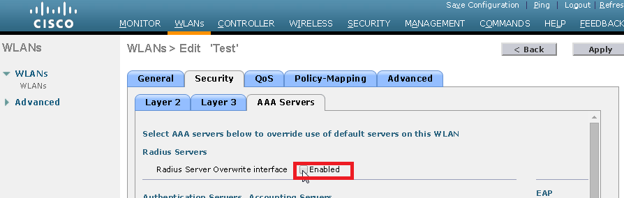
- Management Interface – communication with the WCS, the MSE, Lightweight Directory Access Protocol (LDAP) servers, and RADIUS servers. We can force the dynamic interface associated with the WLAN to be used instead by checking
- Dynamic interface – used to relay DHCP traffic to DHCP server
- AP manager interface – communication with CAPWAPs
References:
- CCNP Wireless (642-732 CUWSS) Quick Reference Guide by Jerome Henry
- IPexpert’s CCNP CUWSS Wireless Voice on Demand (642-731)
