Evolution of WCS
Cisco WCS (no longer supported) -> Cisco Prime Network Control System (NCS) -> Cisco Prime Infrastructure (PI): Works with both wired and wireless.
WCS
Hosted on 32-bit Windows 2003 SP1+ or Red Hat Linux ServerHas 2 Forms
- WCS Base ( clients located in relation to nearest AP)
- WCS Plus ( clients location more accurate and can also use MSE for tracking).
Licencing
- Single Server Licence for 50, 100 or 500 APs
- Enterprise licence (only for WCS Plus) – can support 1 or more server instances with a max of 50000 APs
Cisco WCS Navigator acts as a single interface to access up to 20 distinct WCS servers. This is a separate product.
WLC Page Displays
- Alarm Summary
- Grouped as critical, major and minor
- WCS will remember each alarm for a default period of 15 days or until someone takes some action on it.
- Actions to be performed on Alarms:
Assign to me - remains in your alarm list

Unassign - removed from your alarm list

Delete - WCS will forget about it

Clear - WCS will record it and remove from list

Acknowledge - alarm has been checked and can be removed from the list

Unacknowledge - Alarm is added back to the list

Email notification
- Main Navigation Area
- Functions that can be performed
Monitor

Reports

Administer WCS

Configure - changes to WLCs, APs etc

Services - Intergrate WCS with external services

Tools - Perform audits, attach info to Cisco TAC requests

Help
- Home
- Displays charts and graphs of wireless activity.
- Is customizable for each user
WCS to configure devices
Configure > Controllers (add correct SNMP settings for the controller to be added)
WCS Maps
Monitor > Maps
- WCS maps are organized in a tree-like structure. A campus contains one or more buildings or outdoor areas. Each building can contain one or more floor maps. By default, maps are placed into a system campus.
- WCS computes the RF signal strength for each AP and displays the results as a colored heatmap. Red represents a strong signal (–35 dBm), progressing through orange, yellow, green, and then blues and purples at the weak end of the scale
(–90 dBm). - WCS updates the AP icons based on current conditions. A green icon – AP radio that is working properly, with no faults or alarms. A yellow icon – AP radio with a minor alarm, while a red icon indicates a major alarm.
In summary, the interface for the WCS is similar to the Prime Infrastructure Interface. Since PI is what I have for now, I will show you the interface that it has. Please note that PI is not covered in the CCNA series so this is just additional information for those who want 🙂
Home

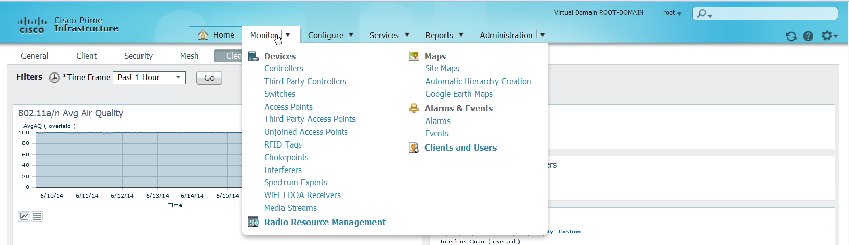
What you can access from Cisco Prime Infrastructure Monitor Interface
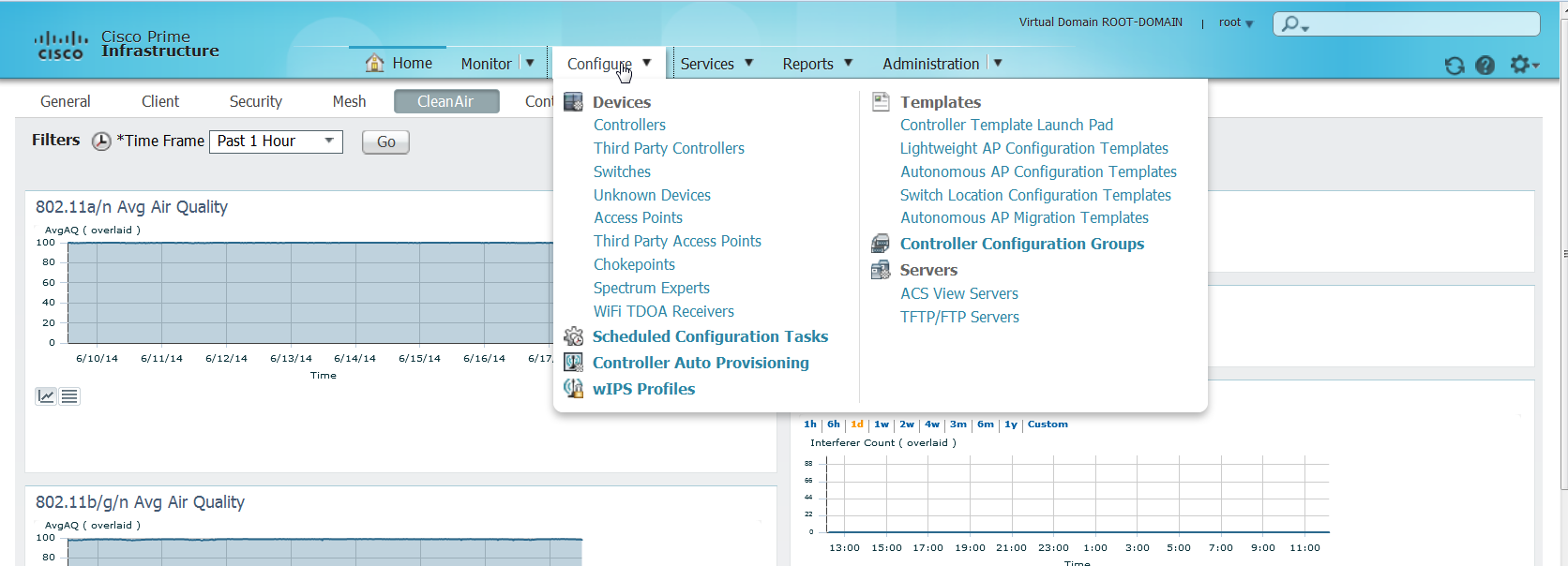
Configure Interface
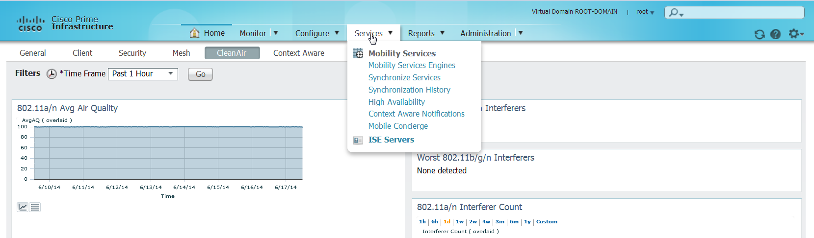
Services allow you to add access to external services like MSE for tracking
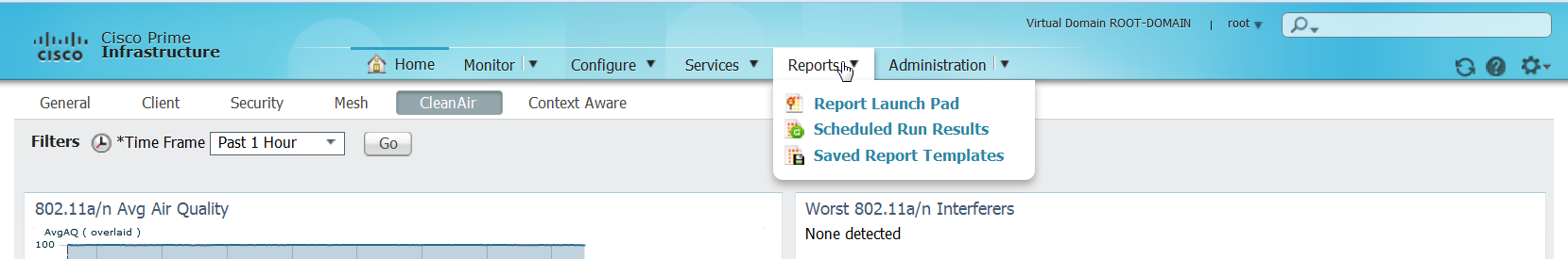
The report tab can be used to generate reports
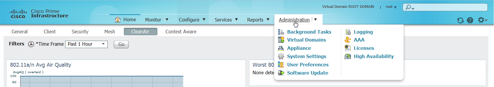
The Administration tab can be used to configure the PI itself
Oh, Forgot to mention that the alarms were moved to the bottom for the PI

Last but not least, the most interesting part of it all offcourse is the site map 🙂

