Exam Topic 3: Wireless LAN Design
Controller Redundancy Design:
- Deterministic
- Dynamic
Deterministic Controller Redundancy
- Ap is configured with
- Primary Controller
- Secondary controller
- Tertiary controller
- DisAdvantages
- More planning required
- More configuration
- Advantages
- Better predictability
- Faster failover times
- Network stability
- Flexible and powerful redundancy design options
- Fallback incase of failover
- Recommended best practice
- Examples:
- N+1
- N+N
- N+N+1
N+1 WLC Redundancy
- 1 WLC acts as backup for several WLCs
- Backup is configured as secondary WLC on each AP
- Disadvantages:
- Backup may become oversubscribed incase of too many failures on primary WLC
- Backup is normally placed in DataCenter

N+N WLC Redundancy
- Equal numberof WLCs back up each other
- Should be enough capacity to manage failover on each WLC

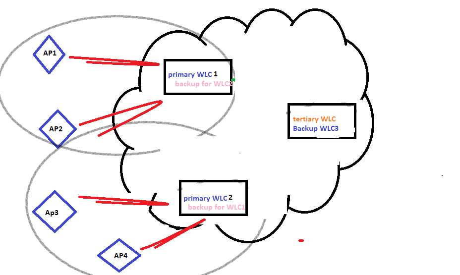
N+N+1 WLC Redundancy
- Equal number of WLCs backup each other
- Backup WLC configured as tertiary for APs
Dynamic Controller Redundancy
- Uses CAPWAP to load balance APs across WLCs
- CAPWAP populates AP with backup WLC
- Best used when WLCs are organised in a centralized cluster
- Disadvantages
- Longer failover times
- unpredictable operations
- more intercontroller roaming
- no fallback options if WLC fails
- Advantages
- Easy to deploy
- Easy to configure
- APs dynamically load balance
- Example
- Adjacent APs register to different WLCs
Radio Management and Radio Groups
- Recommended:
- Limit numbe of data devices connected to AP = 20
- < 7 concurrent Voice over WLAN calls using G711
- < 8 VoWLANs calls using G.729
Cisco Radio Resource Management (RRM) Algorithm
- Used to managed AP RF channel and power configuration
- Used by WLCs to automatically configure, optimize and power configuration
- Functions:
- Radio resource monitoring: LWAPs monitors all channels and sent the gathered packets to the WLC which in return checks for rogue APs, cliients and interfering APs
- Dynamic channel assignment: WLCs automatically assign channels so as to avoid interference
- Interference detection and avoidance: LWAPs monitor all channels and detect interference by a predefined threshold (default = 10%)
- Dynamic transmit power control: WLCs dynamically adjust power levels
- Coverage hole detection and correction: WLCs may adjust the power output of APs if clients report that a low received signal strength indication (RSSI) level is detected
- Client and network load balancing: to maintain network balance, clients can be influenced to join certain APs
- AP selfhealig
- WLCs useRRM to
- raise power levels
- adjust channel selection of neighbour AP to compensate for lost coverage of failed AP
- WLCs useRRM to
- AP is considered a lost neighbour if neighbour messages are no longer received at -70dBm
RF Groups
- Cluster of WLCs that coordinate using their RRM calculations.
- If a neighbour message sent from one AP to another is above-80dBn,WLCs form an RF group
- WLCs select RF leader
- Leader uses UDP port 12114 for 802.11b/g/n and UDP port 12115 for 802.11a to exchange messages with group members
- WLCs analyze RF data
- WLCs select RF leader
Group formation
- APs exchange neighbour messages with encrypted shared key configured in WLC and sent to APs
- APs with same secret key can validate messages from each other. If message is over -80dBm – RF Group is formed
- RF Group members elect group leader to maintain master power and channel scheme for RF group.
- Group leader analyzes real time radio data collected by scheme and calculates master power
RF Site Survey
- Used for:
- determine design parameters for WLANs
- determine customer requirements
- determine coverage areas
- check RF interference
- determine placement of APs
Steps:
- Define customer requirements
- Service level
- VoIP support
- Devices to support
- Site where APs will be located
- Get a facility diagram to check for RF obstacles
- Inspect facility visually. Check for RF barriers eg. metal racks, stairs, elevator shafts
- Identify user areas that will be intensly used and those that will not be heavily used
- Determine preliminary AP locations
- Perform actual survey by using AP
- RF strength
- check effects of the electrical interference
- Document findings. Record:
- Target AP locations
- log signal readings
- data ratesat outer boundaries
Final report should have:
- Detail customer requirements + Diagram AP coverage
- Parts list
- Survey tools used
- Survey methods used
Using Ethernet over IP (EoIP) Tunnels for Guest Services
Ways of securing guest traffic from corporate traffic:
- Segregate traffic using separate VLANs
- Broadcast guest SSID but dont broadcast corporate SSID
- Configure security features
- Use EoIP tunnel
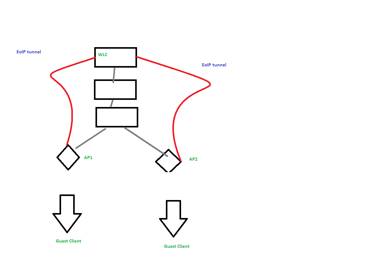
EoIP Tunnel
- Used to tunnel guest traffic from the edge CAPWAP AP to anchor WLC
- Used to logically segment guest traffic
- N need for guest VLANs in network
- Ethernet frames from guests are maintained in the tunnel
Wireless Mesh for Outdoor Wireless
Traditionally:
- Each AP is wired to network
- Limited to point to point and point to multipoint bridging between buildings
Wireless Mesh solution:
- No need to wire each AP
- Users can roam from one area to another without having to reconnect
Mesh components:
- Wireless Control System (WCS) – SNMP management system
- WLC
- links mesh APs to wired network
- AP Management
- Mitigate radio interference
- manage security
- L3 mobility
- Rooftop AP (RAP)
- connects mesh to wired network and serves as root
- communicates with MAPs
- placed on roof tops or towers
- Mesh AP (MAP)
- provide access to wireless clients
- communicate with RAP
- usually located on top of a pole

Mesh Design Recommendations
- < 10 ms latency per hop (typical: 2 – 3 ms)
- Outdoor:
- < 4 hops recommended.
- Maximum 8 hops supported
- Indoor
- 1 hop supported
- (Recommend) 20 MAPs per 1 RAP
- Max 32 MAPs per RAP
- Throughput:
- 1 hop = 14 Mbps
- 2 hops = 7 Mbps
- 3 hops = 3 Mbps
- 4 hops = 1 Mbps
Campus Design Considerations
№ of APs
- 20 devices per AP
- 7 G.711 concurrent VoWLAN calls
- 8 G.729 concurrent VoWLAN calls
AP Placement
- Centralized location
AP Power
- PoE prefered
Number of WLCs
- Depends on redundancy model (deterministic recommended)
- Depends on number of required APs
- Depends on number of supported APs on WLC
WLC Placement
- Secure wiring closet or DC
- Minimize intercontroller roaming
- Can be centralized or distributed
Wireless APs

| AP 1130 | |
| Data uplink | 10/100 |
| Power Requirement | 802.3af |
| Installation | Carpeted Office |
| Temp Range | 0 to 40C |
| Antennas | Internal |
| WiFi Standard | a/b/g |
| DRAM | 32 MB |
| Flash | 16 MB |

| AP 1140 | |
| Data uplink | 10/100/1000 |
| Power Requirement | 802.3af |
| Installation | Carpeted Office |
| Temp Range | 0 to 40C |
| Antennas | Internal |
| WiFi Standard | a/b/g/n |
| DRAM | 128 MB |
| Flash | 32 MB |

| AP 3500i | |
| Data uplink | 10/100/1000 |
| Power Requirement | 802.3af |
| Installation | Carpeted Office |
| Temp Range | 0 to 40C |
| Antennas | Internal |
| WiFi Standard | a/b/g/n |
| DRAM | 128 MB |
| Flash | 32 MB |

| AP 1240 | |
| Data uplink | 10/100 |
| Power Requirement | 802.3af |
| Installation | Rugged |
| Temp Range | 20 to 55C |
| Antennas | External |
| WiFi Standard | a/b/g |
| DRAM | 32 MB |
| Flash | 16 MB |

| AP 1250 | |
| Data uplink | 10/100/1000 |
| Power Requirement | E-PoE 802.3af |
| Installation | Rugged |
| Temp Range | 20 to 55C |
| Antennas | External |
| WiFi Standard | a/b/g/n |
| DRAM | 64 MB |
| Flash | 32 MB |

| AP 1260 | |
| Data uplink | 10/100/1000 |
| Power Requirement | 802.3af |
| Installation | Rugged |
| Temp Range | 20 to 55C |
| Antennas | External |
| WiFi Standard | a/b/g/n |
| DRAM | 128 MB |
| Flash | 32 MB |
| AP 3500e | |
| Data uplink | 10/100/1000 |
| Power Requirement | 802.3af |
| Installation | Rugged |
| Temp Range | 20 to 55C |
| Antennas | External |
| WiFi Standard | a/b/g/n |
| DRAM | 128 MB |
| Flash | 32 MB |
Branch Design Considerations
Recommendations:
- Consider Number of APs
- Consider placement of AP
- Consider physical location
- Consider expected number of WLC clients in office
- RTT between AP and WLC < 300ms
- For centralized WLCs use REAP or HREAP
Local Media Access Control (MAC)
- Supported by CAPWAP
- AP provides MAC management support for association requests and actions
- Client traffic is terminated at the wired port of the AP and not at the WLC
- Traffic does not have to traverse WLC
- WLAN clients continue to function even if WAN link is down
Remote-Edge AP (REAP)
- Used to support remote offices
- Extends controller timer
- Traffic is encapsulated in LWAPP tunnel and sent to WLC
- Management control + RF Management done over WAN
- Client data is locally bridged
- Local clients still have connectivity in the event of a WAN failure
- Support layer 2 security policies only
- No NAT support
- Need a routable IP add
Hybrid Remote-Edge AP (H-REAP)
- REAP enhancement
- Supports NAt
- More security options
- Can control up to 3 APs remotely
- Prefered option for remote and small office
- Delay sensitive. RTT between AP and WLc should be <300ms
- CAPWAP must be prioritized over other traffic
Security modes:
- Standalone
- When WLC is unreachable, HREAP can authenticate the client
- Supports WPA-PSk, WPA2-PSk for clients
- Connected
- Client authentication is done by WLC
- Supports WPA-PSk, WPA2-PSk, VPNs, L2TP, EAp and web authentication for clients
Branch Office Controller Options
Recommended:
- WLC 2100 for 25 APs
- WLC 4402-12 for 12 APs
- WLC 4402-24 for 24 APs
- WLC Module in ISR for 25APs
- 3750 with WLC for 25 or 50 APs
UDP Ports for Wireless protocols
| LWAPP control | UDP 12223 |
| LWAPP data | UDP 12224 |
| WLC exchange messages (unencrypted) | UDP 16666 |
| WLC exchange messages (encrypted) | UDP 16667 |
| RF group IEEE 802.11b/g | UDP 12114 |
| RF group IEEE 802.11a | UDP 12115 |
| CAPWAP control | UDP 5246 |
| CAPWAP data | UDP 5247 |
